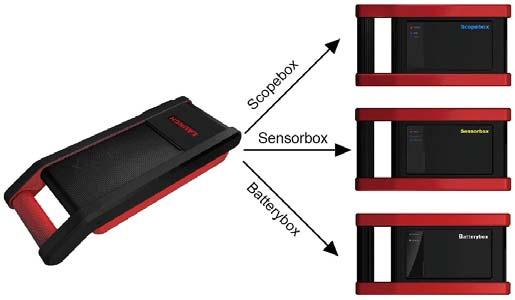
X-431 GDS has an optional function of oscilloscope, which can make the auto repair technician quickly judged the faults on automotive electronic equipment and wiring.
I. Oscilloscope
If using an ordinary oscilloscope to test the electronic equipment, the biggest problem is how to set the oscilloscope (adjust the display parameters of oscilloscope to make the waveform become clear), while using the automotive oscilloscope can make the setting on testing automotive electronic equipment become simple and intuitive (via automatic setting function), just via clicking “Automatic settings”, the waveform can be directly observed without any setting and adjustment.
For some automotive electronic equipment, the signal change rate is very fast, whose cycle reached a thousandth, besides, many fault signals are intermittent, and unsteady, which makes the ordinary equipments, such as decoder, Multimeter etc., hard to capture such fault signal and affects the fault diagnosis and trouble; and the oscilloscope sweep speed is far greater than the signal frequency of such vehicles, usually 5-10 times of the measured signal. The automotive oscilloscope not only can quickly capture the circuit signal, but also can slowly display the waveform to observe and analyze. It can also record and store the tested signal waveform which can be playback to observe for the fast signal, having great convenience to failure analysis. Either high-speed signal (e.g.: injection nozzle, intermittent fault signal) or the slow-speed signal (e.g. the throttle position change and the oxygen sensor signal) can be observed through automotive oscilloscope in an appropriate waveform.
We know that the electronic signal can be compared and judged via testing five parameters indexes. The five parameters indexes are the amplitude (the maximum voltage of signal), the frequency (the cycle time of signal), the shape (the appearance of signal), the pulse width (the duty cycle or the time range of signal), and the array (the repetition characteristic of signal), which can be tested, displayed, saved by the automotive oscilloscope. Via the waveform
analysis can further detect the circuit fault on sensors, actuators, circuits, and electronic control units, etc.
For detailed operations and specifications, please refer to X431 GDS Scopebox user’s manual.
II. Ignition
The ignition system is the system which has greatest impact on the performances of gasoline engine, as the statistical data shows that nearly half of the failures are caused by poor work of electrical system. And the performance tests of engine often start from the ignition system. Nowadays ignition system includes distributor and distributorless. Distributorless includes independent ignition and simultaneous ignition.
– Distributor ignition system: conventionally includes contact breaker (commonly known as the platinum) contact-controlled ignition system and magnet, infrared or hall components breakless ignition system.
– Direct ignition system: crankshaft sensor send out the ignition timing signal and cylinder identification signal for the specified cylinder send out the specified signal in specified time, each cylinder has its independent ignition coil.
– Simultaneous ignition system: two cylinders share one ignition coil, when two cylinder pistons reach top dead center at the same time (one is compression, the other is the exhaust), two spark plugs will be ignited at the same time, at this time, the ignition for the former cylinder with high-pressure low temperature gas mixture, the ignition is valid, while for the latter one with low-pressure high temperature exhaust gas, the ignition is invalid.
X-431 GDS can test and analyze the primary/secondary signal coming from various engine ignition systems.
For detailed operations and specifications, refer to X431 GDS Scopebox user’s manual.
III. Sensor
Vehicle sensors are the signal input devices for electrical control systems, which can transform all kinds of running parameters, such as vehicle speed, coolant temperature, engine RPM, air flow, throttle opening, etc., into the electronic signal for the vehicle computer who can optimize the engine running status per the above-mentioned parameters to keep the engine working in a prime status.

As the sensors can be separated into many types, when you troubleshoot a related-sensor fault, you shall focus not only on the sensor itself, but also the whole trouble circuit and variety of sensor’s parameters while running. “Sensor simulation test” function is specially developed to diagnose and simulate vehicle sensor faults, including “DC voltage simulation”, “Fixed frequency simulation”, “Predefined waveform simulation”, and “Hand-drawing waveform simulation”, which can help customer to diagnose and simulate the
vehicle sensors quickly and conveniently.
For detailed operations and specifications, refer to X431 GDS Sensorbox user’s manual.
IV. Multimeter
X-431 GDS provides an optional function of “Multimeter”, by which, you can perform voltage, resistance or frequency test.
For detailed operations and specifications, refer to X431 GDS Sensorbox user’s manual.
V. BatteryTest
X-431 GDS provides an optional function of “BatteryTest”, which adopts the most advanced conductance testing technology in the world, detects the vehicle battery status and provides in-vehicle and out-vehicle testing modes.
In-vehicle testing can complete charging system and ignition system testing.
Several battery standards and regulars are supported, including CCA, DIN, IEC, EN, JIS, SAE and GB etc.
For detailed operations and specification, refer to X431 GDS Batterybox user’s manual.


